The Other Half of the Engine

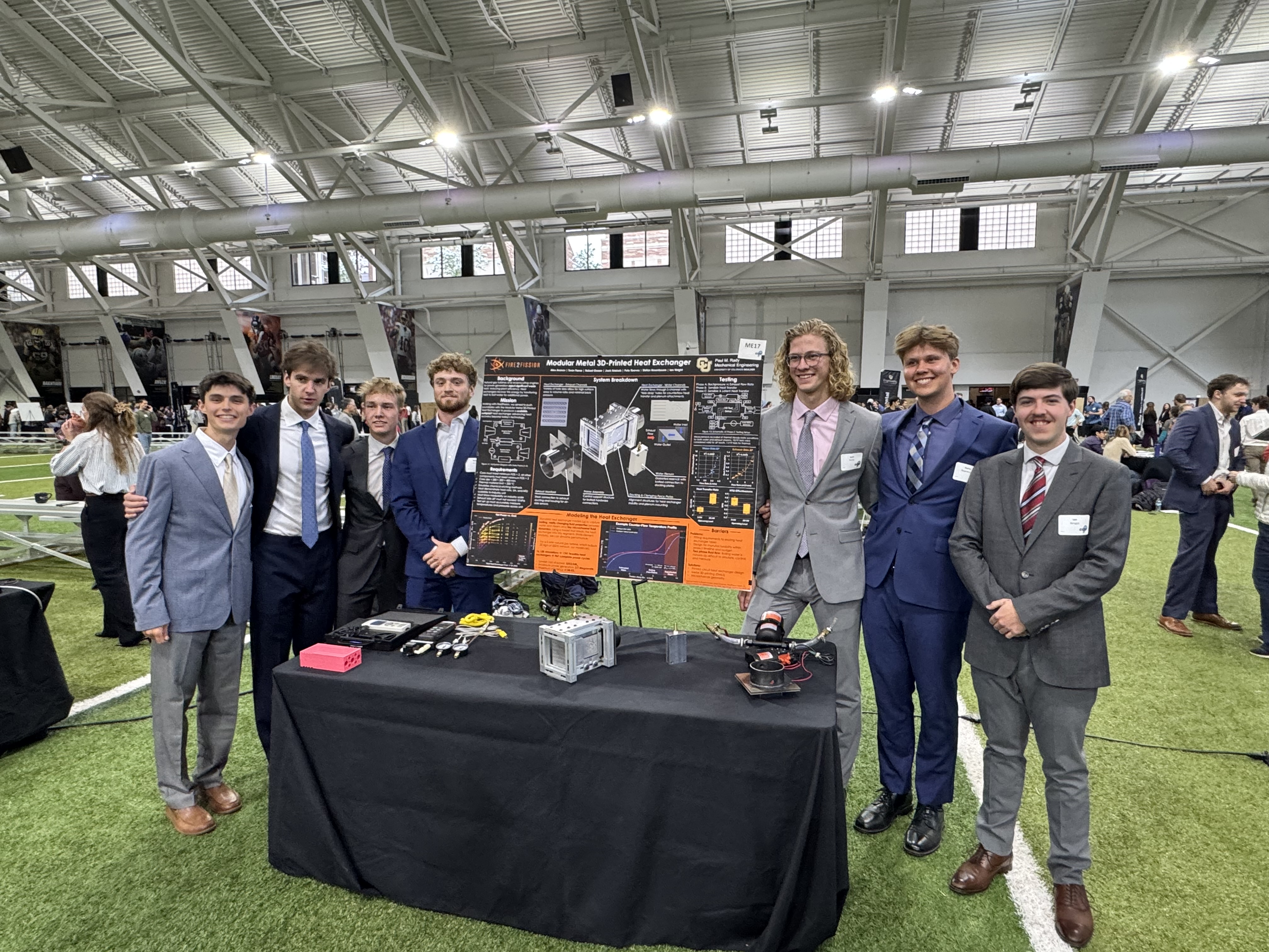
How seven engineers built us a heat exchanger that doesn't exist on the market — and made steam out of a block of aluminum the size of a loaf of bread.
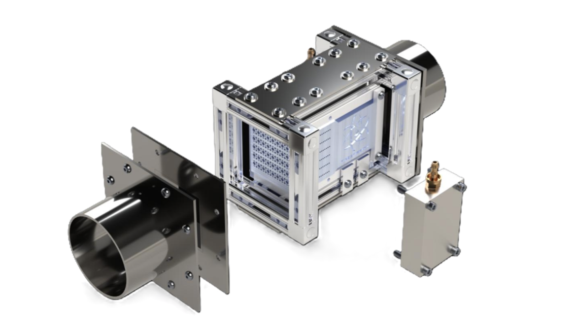
Here's a question I've been chewing on for a while: how much energy does a natural gas engine actually throw away, and what would it take to go catch it?
Every engineer in power generation knows the answer is "a lot." But I'd never sat down and put a real number on it — until we went and built the hardware.
So let's do the arithmetic.
Take the engine we tested on: a Taylor Power Systems TG80, an 80 kW natural gas reciprocating engine. Call its thermal efficiency 35%, which is generous for that class. To make 80 kW of electricity it has to burn about 230 kW of fuel. That means roughly 150 kW walks out the door as heat. Some goes into the jacket water, some radiates off the block, and about a third of the fuel input — call it 75 kW — goes straight up the exhaust stack at 230°C.
Read that again.
For every kilowatt of electricity that engine delivers, it throws away damn near a kilowatt of exhaust heat.
Now scale it. A 5 MW gas turbine — the size class we're actually targeting — dumps roughly 5 MW of recoverable exhaust heat at about 550°C. Every one of them. Every hour they run. And we are currently installing behind-the-meter generation at the fastest rate in modern history to feed data centers that will consume it around the clock.
So what are we waiting for, right?
Right. Here's the problem. 🔥
The technology to catch that heat has existed for decades. It's called a Heat Recovery Steam Generator, and at 100 megawatts it works beautifully.
Below about 10 megawatts, it falls apart. The units are enormous, they're expensive, and each one is engineered for one specific piece of source equipment. Behind-the-meter generation isn't one piece of equipment — it's a chaotic zoo of turbines and reciprocating engines from a dozen manufacturers, sitting on pads that don't have room for a utility-scale steam plant.
Nobody makes a compact, modular, affordable unit that adapts across that zoo. There's a hole in the market shaped exactly like a product.
So in the fall of 2025, we sponsored a senior design team at the University of Colorado Boulder to go build one. Seven mechanical engineers, two semesters, real budget, real hardware, real exhaust.
What they handed back in April was the Modular Heat Recovery Test Unit.
They killed three designs before they built one
This is the part I want you to pay attention to, because it's the part that tells you whether a team can actually engineer.
At the Preliminary Design Review, the architecture was a plate-plate exchanger with snaking internal microchannels. Great surface area. Naturally stackable. Exactly what a modular unit wants.
Then they ran the two-phase physics and it fell apart three ways at once: the confined passages would flood as vapor expanded during boiling, transient boiling introduced a water-hammer risk, and the horizontal channel routing asked steam to climb against gravity.
Then Sean Farrar ran the structural analysis. At 20 MPa, the geometry came back with a factor of safety of 0.02.
The requirement was 2.
Dead. Next.
The finned-tube design that followed was the easy answer. Factor of safety near 4.9. Good surface area density. A mature commercial supply chain that would have cut months off procurement. Every incentive pointed at taking it.
They walked away from it anyway — because a finned-tube architecture forces you to split the exchanger into three separate boxes, a preheater and a boiler and a superheater, before the fluid ever reaches a turbine. That's three times the integration headache at every install we'd ever do, and it throws away the single compact unit that's the entire point.
Choosing the harder path when the easy one is sitting right there is what separates engineering from parts selection.
The third pivot was ours. The team had built a serious case for supercritical CO₂ as the working fluid — and the case was good. It eliminates two-phase boiling entirely. It expands about 5x across the exchanger instead of water's 1,000x. sCO₂ turbines run roughly 10% more efficient than steam.
Technically superior. Commercially unusable.
Almost nothing installed in the field today can accept sCO₂. Picking it would have shrunk our addressable market to nearly zero, and we told them so. Water stayed — and they solved the expansion problem with design instead, specifying roughly 10 MPa on the water side at full scale, which drops the liquid-to-vapor expansion from 1,000x to about 10x.
That's the whole job. Not "what's the best physics." What's the best physics that someone will actually buy.
A $78,000 part for $6,000
The core was always going to be a printed circuit heat exchanger — chemically etched plates, diffusion bonded into a solid block, thousands of parallel microchannels. Highest surface-area density in production. It also only pencils out at volume, and prototype quotes came back well past the entire project budget. Casting had the same problem. Machining couldn't guarantee a watertight seal across a stacked microchannel network at temperature and pressure.
Which left additive manufacturing, and a partner twenty minutes up the road: Elementum 3D, printing in AL6061-RAM2, an aluminum they developed in-house specifically for laser sintering, held to ±0.005 inches on interior geometry.
First quote, filling their EOS M400 build volume: approximately $78,000.
That single part eats the entire project. No pumps, no heaters, no ducting, no sensors, no frame.
A weaker team accepts a worse design. This one went back to the physics and asked how small the core could get while still exercising the regime that mattered.
Answer: 75 x 75 x 150 mm. About $6,000. Same geometry, same channel sizing, same boiling behavior, 8% of the cost.
Inside that block sit hundreds of circular microchannels down to 1.5 mm across, separated by walls as thin as 0.8 mm. Water runs an S-bend path for true counterflow. Exhaust runs straight through, sized to keep pressure loss down.
The result is 612 m² of heat transfer surface per cubic meter of core. A conventional shell-and-tube exchanger gets you about 100. A finned tube, about 400.
Nobody sells the software, so they wrote it 📝
Before any of that could be ordered, somebody had to predict how it would behave.
They evaluated the commercial tools — ANSYS, SimScale — and threw them out. Those correlations assume constant fluid properties and conventional shell-and-tube or plate geometry. None of that describes water boiling across thousands of parallel microchannels.
So they built their own: a 1D counter-flow finite-volume PCHE solver coupled to a four-state Rankine cycle, pulling Shah and London and Gnielinski for single-phase flow, Kandlikar for flow boiling, Churchill for friction factor, Friedel for two-phase pressure drop. It sweeps the entire geometry and operating space across every available CPU core and spits out Pareto fronts, sensitivity analyses, and cost per kilowatt-electric.
Now here's the part worth sitting with.
Several of those correlations were originally derived for conventional tubes, not microchannels. The team knew that going in. And they had to commit geometry, material, and a non-refundable manufacturing order against a model that could not be validated until the part physically existed.
Order the wrong thing and you lose most of the hardware budget and most of the remaining schedule.
They handled it the only honest way available: benchmark against published 1D-versus-3D PCHE comparisons wherever prior data existed, deliberately scope the sub-scale test envelope to conditions where the correlations were closest to their original validity range, and treat the model as a design-decision tool rather than a performance oracle — until real data existed to make it one.
That model now belongs to Fire2Fission, and we can point it at every site in the portfolio.
Then they ran it on a live engine
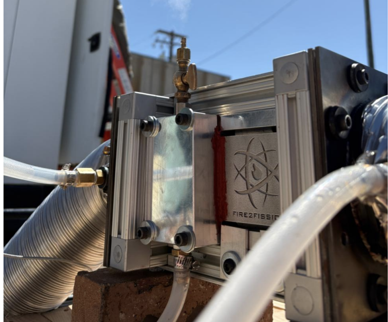
Three test phases. Phase A characterized hydraulics cold. Phase B added sensible heat from an electric blower-heater. Phase C put the unit on the exhaust of that TG80 at Baseline Energy and loaded the engine across its range.
Two results matter.
It held, and it made steam. Heat moved across the microchannel walls with zero leakage between the water and exhaust circuits, confirming core integrity up to about 230°C. At four separate operating points, the unit produced a steady flow of steam — out of six inches of total channel length.
Six inches. That is an absurd amount of heat flux in a very small volume, and it is exactly the proof-of-concept the whole year was built to get.
Backpressure passed with room to spare. This was the hard constraint: exceed 10 kPa and you start choking the engine you're supposed to be helping. Measured exhaust-side pressure loss topped out at 0.98 kPa at 8.6 m³/min, with a regression fit of R² = 0.94. Run that curve out and the unit doesn't hit its own limit until roughly 14.8 m³/min.
On sensible heat transfer, the model predicted NTU within 13–23% and thermal conductance within 7–33% of measurement. For a first-article correlation-based model operating outside the regime its correlations came from, that's a good day.
Caveats, Complications, & Conundrums ✅
Now the part most companies would quietly delete.
Some of the calculated thermal efficiencies came back above 100%. That is thermodynamically impossible, and it means measurement error, not performance. The team said so in plain language in their own report rather than burying it.
The cause isn't mysterious. With the core and hardware consuming nearly the whole budget, every rotameter, thermocouple, pressure gauge, manometer, and DAQ module in the campaign was borrowed in-kind from campus labs. Steam quality was estimated with a bucket and a stopwatch. Outlet water temperature never read above 81°C in tests where we watched steam come out of the unit, which tells you the sensor placement was wrong, not that the physics were.
Open items we're carrying forward:
The model over-predicts exhaust backpressure by about 2x, consistently, across the whole range — which says systematic error, not tuning. Prime suspects are the Friedel multiplier and the lumped-channel-bank assumption. Fixable, but it needs to get fixed.
Precipitate started forming on the core face during Phase C. Probably water vapor from combustion condensing on cool aluminum, possibly minerals out of the gas. Nobody has characterized it, and fouling that grows without bound is a real threat to that beautiful backpressure number.
Nothing was thermally cycled. Every data point was steady-state. We don't know what repeated cold-hot-cold does to the microchannels or the plenum gaskets.
Two-phase measurement needs actual instrumentation. A bucket and a stopwatch got us a qualitative answer. The next round needs a quantitative one.
If you think we got something wrong in here, tell me. Seriously. Every one of those open questions is a place where somebody who's done this before can save us six months.
What we do next
The project closed with the sub-scale unit assembled, all three phases run, the model validated against real data, and a full-scale design package drawn to the exact chemical-etching specs of Photofabrication Engineering — 525 x 1200 x 529 mm, 66 water plates, 132 exhaust plates, 66 buffer plates. The team built that relationship themselves.
The next step is to go build it.
Because the thing underneath all of this isn't a heat exchanger. It's a question about how much energy we're willing to keep throwing away. We are about to build out more distributed generation in this country than we have in fifty years, and every megawatt of it comes with a megawatt of heat headed for the sky.
Catching it doesn't require a breakthrough. It requires somebody to design a box that's small enough, cheap enough, and modular enough to bolt onto the equipment that's already there.
Seven undergraduates just proved the box works.
Team 17, University of Colorado Boulder, Department of Mechanical Engineering: Robert Gosser (Project Manager), Alex Aronov (Logistics Manager), Jack Kriekels (Financial Manager), Sean Farrar (Systems Engineer), Stefan Rosenboom (Test Engineer), Ian Wright (CAD & Manufacturing Engineer), Pete Reeves (Electromechanical Engineer). Advised by Mr. Robert Linden, Dr. Daria Kotys-Schwartz, and Dr. Julie Steinbrenner. Core printed by Elementum 3D. Engine time courtesy of Baseline Energy.
If you're running behind-the-meter generation and you're tired of heating the sky — or you're an engineer who reads all of the above and thinks I could fix that backpressure model — reach out. Let's go chase it.
Subscribe to our newsletter
Never miss an insight. Subscribe for updates on industry developments, new articles, and podcast releases
Invest with Fire2Fission